Meet the Gates Running the Show
In the previous reading, you learned where logic gates fit in the hardware hierarchy. Now it is time to meet the four gates that form the foundation of digital logic: AND, OR, XOR, and NOT.
These gates are simple, predictable, and surprisingly powerful. Once you understand how each one behaves, you can combine them into circuits that perform meaningful computations. Think of these gates as four tiny assistants—each with a very particular personality.
A note on notation: Throughout this reading, gate inputs and outputs are represented as 0 and 1. These are the values you will see in truth tables and on the Competency Demo. But you may also encounter other ways of expressing the same idea:
- 0 / 1 — the binary notation used in this course
- False / True — the logical notation used in programming and Boolean algebra
- OFF / ON — the electrical notation that reflects the physical reality of the circuit
- NO / YES — the plain-English version often used when explaining gates to students
All four representations mean exactly the same thing. A gate that outputs 1 is also outputting True, ON, and YES — they are just different languages for the same underlying concept. The Competency Demo uses 0/1 for inputs and True/False for outputs. That is not a trick — it is a deliberate illustration that these representations are interchangeable.
The AND Gate — The Picky One
We begin with the AND gate. When we draw visual diagrams of logic gates, the symbol for the AND gate looks a little bit like a capital letter D. It takes in two inputs and puts out one output.
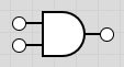
The AND gate outputs a 1 only when all of its inputs are 1. If even one input is 0, the AND gate outputs 0.
Example: Mom tells you that you can go outside and play if you have done your homework and picked up your dirty clothes. BOTH things must be done in order to go out and play. If you only do one she will tell you you can't go.
To better help us visualize the behavior of logic gates, we often draw a truth table. A truth table considers every possible combination of inputs to the gate we are considering. Since an AND gate has two inputs, each of which can be 1 or 0 (also talked about as "on" or "off" or "true" or "false" we create a table with four combinations (22 = 4).
Why AND matters: AND is essential for modeling conditions where multiple requirements must be met at the same time.
The OR Gate — The Generous One
The next gate we consider is the OR gate. When we draw visual diagrams of logic gates, the symbol for the OR gate looks a little bit like a a rocket ship. Like the AND gate, it takes in two inputs and puts out one output.
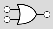
The OR gate outputs a 1 if at least one input is 1. It is far less picky than AND.
Example: Mom tells you that you can go outside and play if you have done your homework or picked up your dirty clothes. If you do your homework, you can go play. If you pick up your dirty clothes, you can go play. If you do both, you can go play. The only time mom says "no" is when you have failed to do both things.
The truth table for the OR gate looks like the following:
Why OR matters: OR captures the idea of "any one of these conditions is enough," which is common in branching logic.
The XOR Gate — The Quirky One
When mom says "do your homework or clean your room" either one is fine. But she will be thrilled if you do both. But suppose you go out to eat and the waitress asks you if you want fries or coleslaw. They are going to be annoyed if you say "both!" In this situation the OR means you have to pick one OR the other. In computer science this scenario doesn't go by the name OR but by the name XOR.
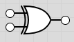
XOR stands for "exclusive OR." It outputs a 1 only when exactly one input is 1. If the inputs match (both 0 or both 1), XOR outputs 0. The logic table for this gate looks like the following:
Example: Phineas and Ferb are the final contestants in the Tri-State Science Fair. The judges have to decide if Phineas or Ferb will win. In the computer, we would have to write "Phineas XOR Ferb" because only one can win.
Another Example: In my living room there is a lightswitch by both doors. If the switches are both down, the lights are off. If I flip up either switch, the lights will turn on. But if I were to flip up both switches, the lights would turn off again.
Why XOR matters: XOR is a key ingredient in arithmetic circuits, parity checks, and bit-flipping operations. It is often where logic starts feeling interesting.
The NOT Gate — The Contrary One
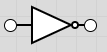
The NOT gate (also called an inverter) takes exactly one input and simply flips it. If the input is 1, the output becomes 0. If the input is 0, the output becomes 1.
The symbol for the NOT gate looks like a triangle. You can easily identify it because, unlike the others, it only takes in one input.
Example: Think of NOT as the student who insists on choosing the opposite of whatever the class decides.
Another Example: Suppose our input is whether it is raining outside and our output is whether we get to go outside for recess. If it is not raining (input A is 0) we get to go outside (output of NOT A is 1). If it is raining outside (input A is 1) we do not get to go outside (output of NOT A is 0).
Why NOT matters: NOT introduces the idea of transformation. It does not combine signals; it alters them, which is essential for constructing more sophisticated circuits.
A Summary Truth Table
As we discussed previously, a truth table lists all possible input combinations for a gate and the output associated with each combination. The following truth table shows our four base logic gates all together and helps us
- learn each gate's behavior
- predict the output for a set of inputs
- trace through larger circuits
- explain CS concepts clearly to others
Patterns to Notice
As you study the four base gates, you might observe a few helpful patterns:
- AND requires full agreement to output 1.
- OR accepts any input that is 1.
- XOR rewards disagreement.
- NOT always flips the script.
Recognizing these patterns makes working with gates (and later circuits) much easier.
Where These Gates Show Up in Real Hardware
You will never see these gates individually on a CPU—they are far too small. But billions of them work together inside every processor to implement:
- arithmetic operations
- memory storage and retrieval
- data comparisons
- graphics processing
- network communication
- robotics and sensor circuits
Understanding the four core gates gives you a solid foundation for seeing how these large-scale computational tasks arise from simple, rule-based behavior.